

Drainage Channels
Slot Drains
Industrial Floor Drains
Floor Drains
Linear Shower Drains
Stainless Steel Covers and Grates
CIP Station Drains
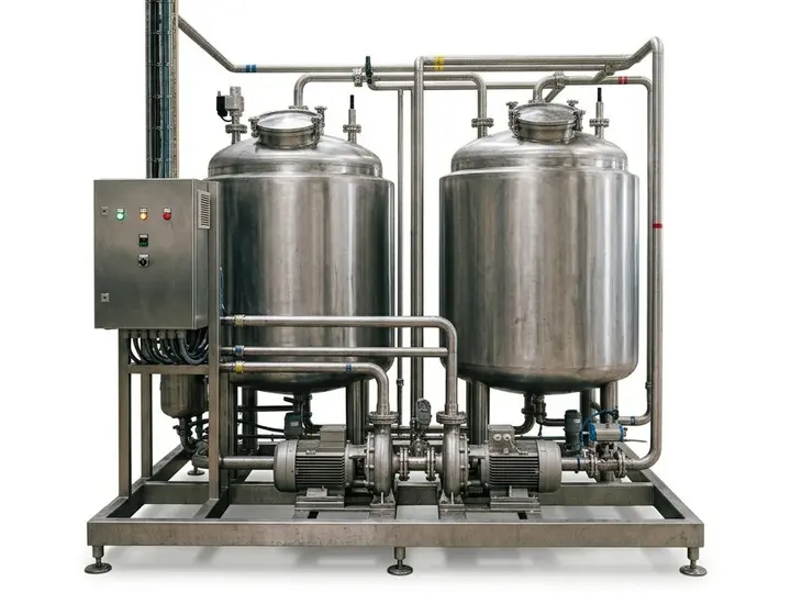
The CIP station has its own specifics. A large volume of water can pass through the installation in a short time, along with the agents used during successive cleaning stages. Temperature, composition of the discharged liquid and discharge intensity all change. All of this must ultimately be collected and removed efficiently.
When designing drainage, the simple statement “there will be a CIP station here” provides little guidance. Predicted flow rate, diameter of the discharge pipe, medium temperature and information on the chemicals used are far more useful. It is also necessary to know the position of the discharge relative to the floor and the drainage system.
Sometimes a single floor drain placed near the discharge point is sufficient. In other locations a channel performs better. Some installations require both solutions to work together.
B&K Group designs and manufactures stainless steel drainage systems for industrial plants. We can prepare a CIP station drainage solution based on the installation documentation and the actual operating conditions.
CIP, or Cleaning in Place, allows process equipment to be cleaned without disassembly. This method is used for pipelines, tanks and other product-contact equipment.
From a drainage perspective, the critical moment is when the medium leaves the installation.
The discharge can be short and intense. Water does not appear on the floor gradually as during normal cleaning. A defined volume of liquid must be collected within a defined time. If the drainage cannot handle the flow, water will pond or spread beyond the discharge point.
That is why instantaneous flow rate is essential at a CIP station. Average wastewater volume over a production shift does not answer the question the drainage system must solve: how much liquid will arrive at peak demand?
Starting a project by asking for channel dimensions reverses the correct sequence.
The first data required concern the installation itself: volume of medium, discharge duration, pipe diameter, temperature and cleaning chemicals. Equally important are the location of the station relative to the drainage system and the way the liquid will reach the drain.
During a retrofit many of these parameters are already fixed. The floor is finished, equipment is in place, pipe routes are set, and the existing sewer connection often cannot be moved without major disruption. The design must then be fitted into an already operating space.
A new-build project allows the positions of floor drains, channel routes, floor slopes and connection points to be coordinated with the process before the floor is poured. This shortens the path from discharge to outlet and reduces the risk of later modifications.
The size of the visible grate does not yet indicate how much water the entire system will accept.
Capacity depends on the construction of the drain or channel, outlet diameter, location, slope and the performance of the downstream drainage network. If any of these elements restricts flow, a larger channel in front of it will not solve the problem.
It is possible to have a channel that can easily accept water from the CIP zone yet still observe ponding. The cause may be the outlet or a further section of the drainage system that cannot remove the discharge at the same rate. Capacity must therefore be considered for the entire drainage path, not only the visible element.
When the medium leaves the installation at one well-defined point, point drainage is the natural choice.
An industrial floor drain can be placed close to the discharge and sized for the expected volume. This minimises the distance water travels across the floor.
Capacity alone does not close the subject. The drain remains part of the production area, so access for cleaning and inspection, connection to the floor and outlet diameter are all important. B&K Group offers floor drains with removable trap and sediment basket that can be extracted without dismantling the entire unit.
If liquid appears over a larger area, flows from several points or the zone itself is cleaned intensively, a channel provides a greater collection surface than a single floor drain.
The channel can run along equipment, cross the production zone or be placed where floor slopes direct the water. Length, width and outlet position are then determined by hall geometry and the volume that must be removed.
B&K Group also manufactures stainless steel sewer channels in project-specific dimensions. The current product page lists load classes from A15 to F900; material and sheet thickness are selected to meet the required class.
This matters in zones used by internal transport. A channel next to equipment travelled by personnel operates under different conditions from one crossing a forklift route. The load class must therefore reflect the actual use of that specific location.
A floor drain and a channel do not have to compete. In one zone the point drain can handle the main CIP discharge while the channel collects water from equipment and floor cleaning.
Slot channels are suitable where a large open collection area is not required. They occupy little floor space and allow drainage to run along equipment or a specific section of the zone.
With a large discharge it is still necessary to verify that the slot design can accept water fast enough. When peak flow occurs at only one location, combining a slot channel with a receiving box may be the solution. The channel then serves the rest of the zone while the larger collection area is placed where it is actually needed.
Drainage at a CIP station contacts whatever leaves the installation after each cleaning stage. This is not always water at ambient temperature.
Acidic and alkaline agents, varying concentrations and elevated temperatures can occur. These details should be known before material selection, because the generic term “stainless steel” is too broad.
B&K Group uses V2A and V4A stainless steel. The manufacturer’s data sheet recommends V2A for standard industrial applications and V4A for more aggressive chemical environments.
For any specific installation the material must still be chosen according to the actual operating conditions: medium, chemicals, concentration and temperature.
The difference appears at the very beginning of the project. In a new hall, process equipment, floor, drainage system and sewer connections can be built in parallel. Once the station location and discharge routes are known, positions of floor drains and channels can be planned immediately.
In an operating plant there is usually less room for manoeuvre. A CIP station is not moved simply because a floor drain would be easier to install half a metre away. The same applies to existing sewer connections and floor construction. The first step is to determine which elements can be altered without disrupting the rest of the process and which must remain in place.
Sometimes it is enough to modify the collection method at a single point. In other layouts a new channel section or a custom-shaped element may be required. Custom fabrication allows the drainage system to be adapted to the existing hall instead of forcing the project around standard product dimensions.
Two stations of similar capacity do not necessarily have identical surroundings. They differ in equipment layout, pipe routes, sewer connections, floor construction and available space for outlets. In such projects the ability to manufacture to exact dimensions has real practical value.
B&K Group also executes custom orders and works from technical documentation. The company accepts, among others, DWG, DXF and sketch files.
From this information the geometry of channels and floor drains, outlet positions and the method of integrating the elements into the zone layout can be defined.
A complete set of execution drawings is not required for the first enquiry. A floor plan, CIP station location and available discharge data are enough to start the discussion.
CIP stations operate in breweries, dairies, bottling plants, meat-processing facilities and other food-processing plants. B&K Group supplies drainage systems for, among others, the meat and fish industry, breweries and wineries and beverage bottling plants.
Conditions in these plants are not identical, however.
The process in a brewery differs from that in a dairy. A bottling line has its own layout, and drainage in a meat-processing CIP zone may operate simultaneously with a system collecting water from intensive floor and equipment cleaning.
When designing, the specific process provides more information than the industry name alone. Once discharge parameters and zone layout are known, the right solution can be selected.
At a CIP station the discharge and the point at which it must be collected must be established first. Only then can the type of drainage, its dimensions, material and connection to the sewer system be decided.
B&K Group designs and manufactures stainless steel drainage systems for industrial plants. Depending on the project, the solution may be based on a single floor drain, a channel or a combination of several elements.
Are you designing a CIP station or modernising an existing installation? Send us the technical drawing and available discharge data. We can then prepare drainage matched to the specific working conditions.
Contact your dedicated account manager — we will prepare a solution tailored to your facility and processes.
Contact us